A few month ago I bought a little rover (controlled by an Arduino Uno) for a very good price. The kit was very complete: Car chassis, 2 Car Wheels, 2 DC Gear Motors, a UNO R3, an L298N Dual H-Bridge Motor Controller and several other components.
This rover is meant to be programmed for autonomous operation. Hence an ultrasonic sensor and a servo is also added in the kit. Also a nice Arduino sensor shield 5 is in the kit. Yes, it was a real bargain 😉
But my idea was to use both an Xbox One Controller and the Firmata protocol to drive this one by myself or one of my sons. And it works very well!
Here is a video of the final solution:
In this blog, I will show you how it’s done.
This is part 2 of a series of blogs about the Xbox One controller:
- Part 1: Using your Xbox One controller in a UWP app
- Part 2: Control your Arduino Rover using Firmata and Xbox One Controller
The main parts used in this project are:
- A rover kit (we use for this demonstration only a subset of the parts: the base plate, the wheels, the motors, the Arduino Uno, the 9 volts battery holder and the L298N Dual H-Bridge Motor Controller)
- An extra battery holder for 6 AA batteries
- A Bluetooth module (HC-06)
- An Xbox One controller with wireless adapter for windows (to connect it to a laptop)
- A laptop (with Windows 10 + VS2015 + Bluetooth dongle)
- A Flashing light for dramatic effect only
Building the kit
Building the kit is not that hard. Although the construction manual was in Chinese, it all seems pretty logical. There is only one baseplate so I had to put some components on top of it and some at the bottom (now the motor controller):

In this picture, two different battery holders are added. During programming, I found out that I had to use a separate power supply just to get the motors running.
Connecting the motors – pin layout of controller
The heart of the hardware, this time, is not the Arduino Uno but the motor controller.
“The L298 is a dual H-bridge driver for DC brushed motors and stepper motors. It supports a wide operating voltage range and can deliver 2 A per channel in a through-hole package that is accessible for do-it-yourself projects.”
This controller will control the speed and direction of each of the two motors, using signals coming from the Arduino.

The pin layout of the L298N Dual H-Bridge Motor Controller is:
- Plus + of DC motor 1
- Minus – of DC motor 1
- Power IN. I supply 9 volts from a separate battery holder
- Common ground. Connected to both my separate battery holder and the Arduino
- Power out. Can produce 5 volts (not used. My Arduino gets power from another battery holder)
- ENA connected to Arduino D10. This port is capable of PWM (white)
- IN1 connected to Arduino D9. (gray)
- IN2 connected to Arduino D8. (purple)
- IN3 connected to Arduino D7. (blue)
- IN4 connected to Arduino D6. (green)
- ENB connected to Arduino D5. This port is capable of PWM (yellow)
- Plus + of DC motor 2
- Minus – of DC motor 2
- The jumper next to 2 and 3 is NOT removed because I do not exceed the input power over 12 volts (up to 35 volts) (jumper not marked in the picture)
Note: the controller has it’s own power supply. The Arduino has one too. To keeps things running (without blowing thins up, give them a common ground. See bullet 4 above)
Connecting the motors – pin layout of Arduino
Connecting the Arduino is pretty straightforward. We connect the ground and the 5 volts of the power supply to the Arduino. And we connect the six lines (ENA, IN1-4 and ENB) to pin D10 till D5.
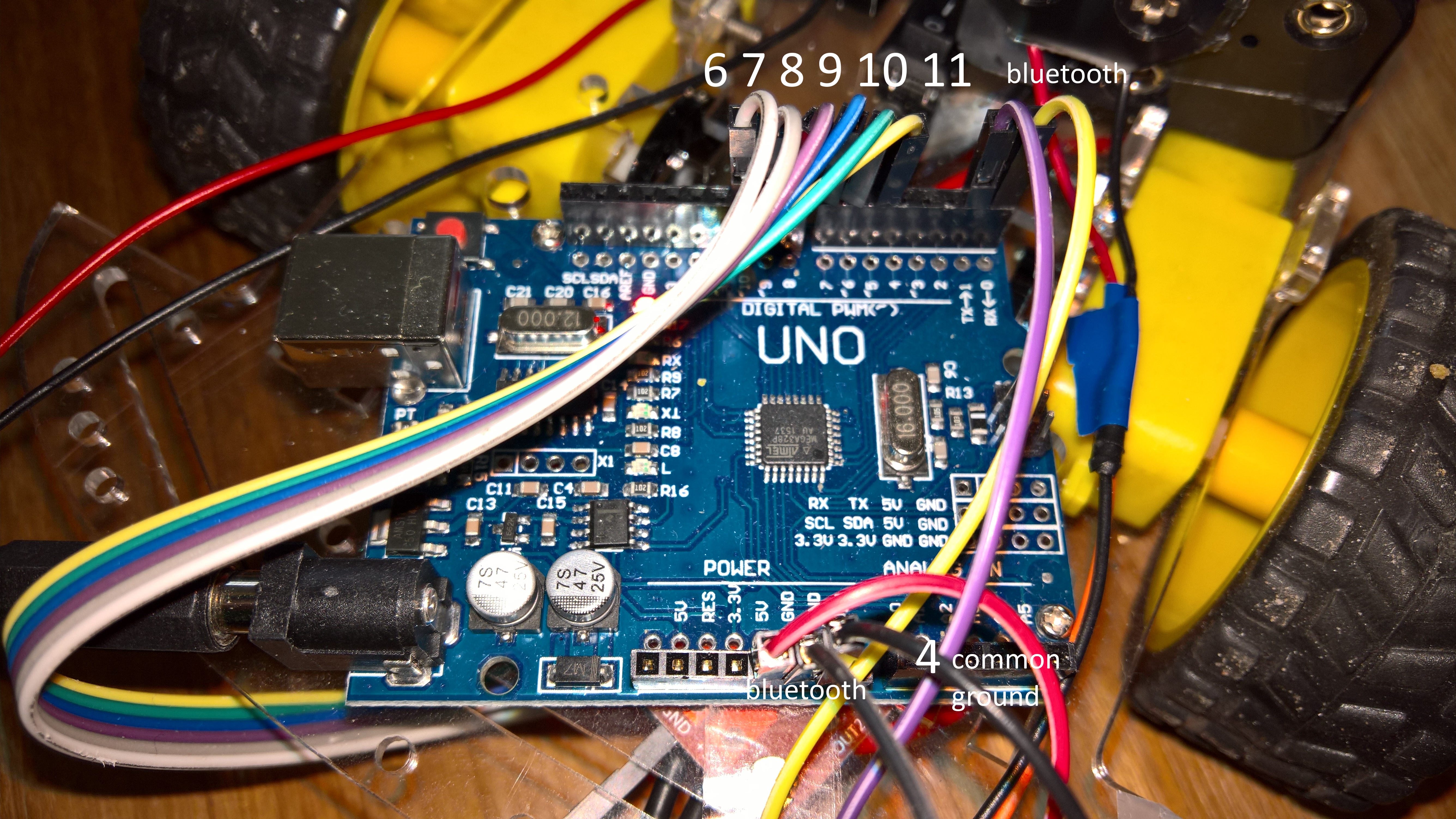
It must be clear that port 7 and 8 (and 9 and 10 for the other motor) are just regular GPIO port. These will be used for the direction of the motor. If both ports (eg. 7 and 8) are LOW, the motor will do nothing (it stops). If one is HIGH and the other LOW the motor will run in one direction. If connected the other way around (the first one is set to LOW and the other to HIGH) the connected motor will run in the other direction.
But.. just setting these pins will result in nothing. No moving parts yet!
The magic will come from pin 5 and 10. These are ‘special’ pins which can generate a PWM signal. Setting a value between 0 and 255 will result in running the motor VERY slow (stopped) or at high speed.
Note: Each port on the Arduino Uno capable of PWM are marked with a tilde (the ~).
Connecting the Bluetooth
The Bluetooth module I use only needs to be connected to the RX and TX port (cross the lines) and it needs 5-volt power and ground from the Arduino.
Firmata sketch on the Arduino
The Firmata sketch “StandardFirmata” is all we need on the Arduino! Just get it from the Arduino IDE examples and upload it (maybe you need to unpin the TX/RX first to complete the upload).
Note: due to the lack of quality of my Bluetooth module, I always lower the baud rate which is hard coded inside the sketch, and set it to 9600.
Gentlemen, start your engines
Or, test the connection…
So why am I using Firmata? because it’s easy. How easy? Very easy. And it can even be done without programming. Just start the Windows Remote Arduino Experience app (available in the store and also works on a Windows 10 Mobile device).
First, you will have to connect to the already paired HC-6 Bluetooth module.

When paired, go to the PWM page. Enable digital pin 5 and give it a value of, say, 128.

Beware: the next step will make your motor running. Helmet on and wheels off the floor. You will know why when you see it.
Then go to the Digital page. And flip the switch of digital pin 6.
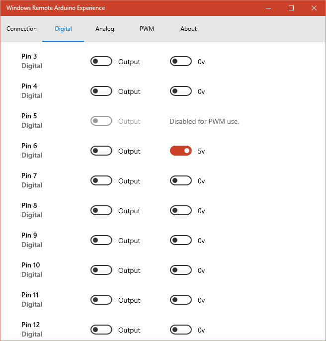
Now, if everything is connected and running, one of the motors will spin!
If so, you can check out other speeds (using a higher or lower PWM value) or change the direction (set digital pin 6 to 0 volt and digital pin 7 to 5 volt).

And there you have it. You can control that wheel!
But there is more, the same goes for pin 10 (PWM) and digital pin 9 and digital pin 8.
Both wheels running. Now start coding…
The UWP app as the match maker
It must be clear we need a new UWP app between the Xbox One controller and the rover.
I already blogged about using the Xbox One controller here. This time we will combine that knowledge with our rover.
Let’s look at the interface of our UWP app:

It’s pretty dull, two buttons and a text block. I will have nothing more to do then first connecting to the Arduino using Firmata. And once the connection is made, the controller button will have to start one giant loop to read the controller input and change it into useful commands.
And what we want to create is this classics tank controls with two handles. All we need is to check the two thumbsticks on the Xbox One controller. Moving them forwards and backwards will also start the corresponding motor forwards and backwards.
Note: If you start a new UWP app, do not forget to add the Bluetooth capability. And you will have to install the NuGet package for Firmata.
First, we add the XAML code in the mainform:
<StackPanel Orientation="Vertical">
  <Button Name="btnStart"
          Click="btnStart_Click"
          FontSize="50"
          Width="400"
          Content="Start" />
  <Button Name="btnController"
          Content="Controller"
          FontSize ="50"
          Width="400"
          IsEnabled="False"
          Click="btnController_Click" />
  <TextBlock Name="tbRead"
             FontSize="20"
             Foreground="Gray" />
</StackPanel>
The code behind of the main form is a bit longer:
public sealed partial class MainPage : Page
{
  private BluetoothSerial _bluetooth;
  private RemoteDevice _arduino;

  private UwpFirmata _firmata = null;
  private Gamepad _Gamepad = null;
  // We never supply a PWM of more then 255 * 0,75
  private double _SpeedLimit = 0.75;
  // values below this absolte value stop the rover
  private double _ActionPoint = 0.15;

  private byte _LeftForward = 6;
  private byte _LeftBackward = 7;
  private byte _LeftValue = 5;
  private byte _RightForward = 9;
  private byte _RightBackward = 8;
  private byte _RightValue = 10;

  private Dictionary<byte, PinState> _CurrentPinStates
                           = new Dictionary<byte, PinState>();

  private Dictionary<byte, ushort> _CurrentSpeedValues
                             = new Dictionary<byte, ushort>();

  public MainPage()
  {
    this.InitializeComponent();
  }

   private void btnStart_Click(object sender,
                               RoutedEventArgs e)
  {
    btnStart.IsEnabled = false;

    Gamepad.GamepadAdded += Gamepad_GamepadAdded;
    Gamepad.GamepadRemoved += Gamepad_GamepadRemoved;

    _bluetooth = new BluetoothSerial("HC-06");
    _bluetooth.ConnectionLost += BluetoothConnectionLost;
    _bluetooth.ConnectionFailed += BluetoothConnectionFailed;
    _bluetooth.ConnectionEstablished +=
                                   OnConnectionEstablished;

    _firmata = new UwpFirmata();
    _arduino = new RemoteDevice(_firmata);
    _firmata.begin(_bluetooth);

    _bluetooth.begin(9600, SerialConfig.SERIAL_8N1);

    _arduino.DeviceReady += ArduinoDeviceReady;
  }

  private async void BluetoothConnectionLost(string message)
  {
    await Dispatcher.RunAsync(
      CoreDispatcherPriority.Normal, () =>
      {
        tbRead.Text = "ConnectionLost" + message;
        btnStart.IsEnabled = true;
      });
  }

  private async void BluetoothConnectionFailed(string message)
  {
    await Dispatcher.RunAsync(
      CoreDispatcherPriority.Normal, () =>
      {
        tbRead.Text = "ConnectionFailed" + message;
        btnStart.IsEnabled = true;
      });
  }

  private async void ArduinoDeviceReady()
  {
    await Dispatcher.RunAsync(
      CoreDispatcherPriority.Normal, () =>
      {
        tbRead.Text = "Device Ready";
      });
  }

  private void OnConnectionEstablished()
  {
    var action = Dispatcher.RunAsync(
      CoreDispatcherPriority.Normal,
      new DispatchedHandler(() =>
      {
        DisableEnableButtons(true);

        ArduinoDigitalWrite(_LeftForward, PinState.LOW);
        ArduinoDigitalWrite(_LeftBackward, PinState.LOW);
        ArduinoDigitalWrite(_RightBackward, PinState.LOW);
        ArduinoDigitalWrite(_RightForward, PinState.LOW);
      }));
  }

  private void DisableEnableButtons(bool enabled)
  {
    // Disable all buttons. Otherwise
    //  the 'A' will press the one focussed.
    btnController.IsEnabled = enabled;
    btnStart.IsEnabled = enabled;
  }

  private async void Gamepad_GamepadRemoved(
                                   object sender, Gamepad e)
  {
    _Gamepad = null;

    await Dispatcher.RunAsync(
      CoreDispatcherPriority.Normal, () =>
      {
        tbRead.Text = "Controller removed";
      });
  }
  private async void Gamepad_GamepadAdded(
                                   object sender, Gamepad e)
  {
    _Gamepad = e;

    await Dispatcher.RunAsync(
      CoreDispatcherPriority.Normal, () =>
      {
        tbRead.Text = "Controller added";
      });
  }

   private async void btnController_Click(object sender,
                                          RoutedEventArgs e)
  {
    DisableEnableButtons(false);

    while (true)
    {
      await Task.Delay(TimeSpan.FromMilliseconds(3));

      if (_Gamepad == null)
      {
        continue;
      }

      // Get the current state
      var reading = _Gamepad.GetCurrentReading();

      if (Math.Abs(reading.LeftThumbstickY) < _ActionPoint)
      {
        ArduinoDigitalWrite(_LeftForward, PinState.LOW);
        ArduinoDigitalWrite(_LeftBackward, PinState.LOW);
        sldrLeftSpeed.Value = 0;
      }
      else if (reading.LeftThumbstickY >= _ActionPoint)
      {
        ArduinoDigitalWrite(_LeftForward, PinState.HIGH);
        ArduinoDigitalWrite(_LeftBackward, PinState.LOW);
        sldrLeftSpeed.Value = 255 *
               Math.Abs(reading.LeftThumbstickY) * _SpeedLimit;
      }
      else if (reading.LeftThumbstickY <= -_ActionPoint)
      {
        ArduinoDigitalWrite(_LeftForward, PinState.LOW);
        ArduinoDigitalWrite(_LeftBackward, PinState.HIGH);
        sldrLeftSpeed.Value = 255 *
               Math.Abs(reading.LeftThumbstickY) * _SpeedLimit;
      }

      if (Math.Abs(reading.RightThumbstickY) < _ActionPoint)
      {
        ArduinoDigitalWrite(_RightForward, PinState.LOW);
        ArduinoDigitalWrite(_RightBackward, PinState.LOW);
        sldrRightSpeed.Value = 0;
      }
      else if (reading.RightThumbstickY >= _ActionPoint)
      {
        ArduinoDigitalWrite(_RightForward, PinState.HIGH);
        ArduinoDigitalWrite(_RightBackward, PinState.LOW);
        sldrRightSpeed.Value = 255 *
          Math.Abs(reading.RightThumbstickY) * _SpeedLimit;
      }
      else if (reading.RightThumbstickY <= -_ActionPoint)
      {
        ArduinoDigitalWrite(_RightForward, PinState.LOW);
        ArduinoDigitalWrite(_RightBackward, PinState.HIGH);
        sldrRightSpeed.Value = 255 *
          Math.Abs(reading.RightThumbstickY) * _SpeedLimit;
      }
    }
  }

  private void ArduinoDigitalWrite(byte port, PinState state)
  {
    // ignore duplicate commands
    var exists = _CurrentPinStates.ContainsKey(port);

    if (!exists
           || _CurrentPinStates[port] != state)
    {
      _CurrentPinStates[port] = state;
      _arduino.digitalWrite(port, state);
    }
  }
  private void ArduinoAnalogWrite(byte port, ushort value)
  {
    // ignore duplicate commands
    var exists = _CurrentSpeedValues.ContainsKey(port);

    if (!exists
          || _CurrentSpeedValues[port] != value)
    {
      _CurrentSpeedValues[port] = value;
      _arduino.analogWrite(port, value);
    }
  }
}
Within the loop for checking the controls we decide if a thumbstick is pointing forwards or backwards or is in the ‘stop’ range. After that, we decide what the value will be for the PWM pin.
It’s interesting to see that writing a PWM value is represented in Firmata as writing an analog value to a digital port. There is no special PWM method in the Arduino class.
I have added two methods “ArduinoDigitalWrite” and “ArduinoAnalogWrite” to prevent writing the same value over and over to the Arduino. This will clutter up the communication and degrade the performance of the Arduino. (In a much richer design I added a buzzer. Without ignoring duplicate commands the performance of the buzzer was extremely poor and terrible to hear).
When the motors get the low PMW pulses, the motor is not directly starting to run, it will whine with a very distinctive sound. This is normal behavior. And that’s how I found out I had to add two power sources. First time I connected everything, I thought the controller was broken. Nothing happened. Until I unplugged one of the motors and the other started to whine.
So that’s how it works:

Please share your creations in the comments!
Footnote: the flashing light is not only for dramatic effect. Whenever your creations start moving, please be aware of safety. The contraption is dumb, you are not! Therefore, I had put this light on top of it in the first place.
This article is also featured at hackster.io

Een gedachte over “Control your Arduino Rover using Firmata and Xbox One Controller”
Reacties zijn gesloten.