Using I2C between RPi Master and Arduino Slave

This is part 2 of a serie of blogs about device communication between Arduino, RaspberryPi etc:

  • Part 1: Using I2C to connect two Arduino Nano’s
  • Part 2: Using I2C between RPi Master and Arduino Slave
  • Part 3: Use Bluetooth between Win 10 UWP and Arduino
  • Part 4: Add virtual Arduino ports to your UWP app
  • Part 5: Custom Firmata function called by Windows 10 IoT
  • Part 6: Better long running custom Firmata functions
  • Part 7: Custom servo usage in Firmata
  • Part 8: Using NRF24L01+ modules between arduino’s
  • Part 9: Cheap Arduino mesh using RF24 radio modules

In my previous post I connected two Arduino’s using the I2C protocol. This was a good test for me to understand the I2C communication.

My initial goal was to connect a Raspberry Pi to one or more Arduino’s. Why?

Plain Arduino’s lack the ability to connect to the Internet. But they are terrific in reading sensors. They can read them in near real-time and convert raw data into something meaningful.

A Raspberry Pi lacks the ability to communicate using analog ports and it is considered slow (having a full OS like Raspbian or Windows 10 means that it just has too much on it’s head). But it is good in communication to the internet (read: Cloud; read: Microsoft Azure) and it has lots of memory.

So it is a very interesting architecture to attach multiple Arduino slave to the same Raspberry Pi master. We create our own gateway. This way the Arduino’s can collect interesting data using low cost sensors and the data is represented in a nice Windows 10 IoT Core dashboard app (The RPi has a HDMI connection after all) or sent the data to a Azure Iot Hub.

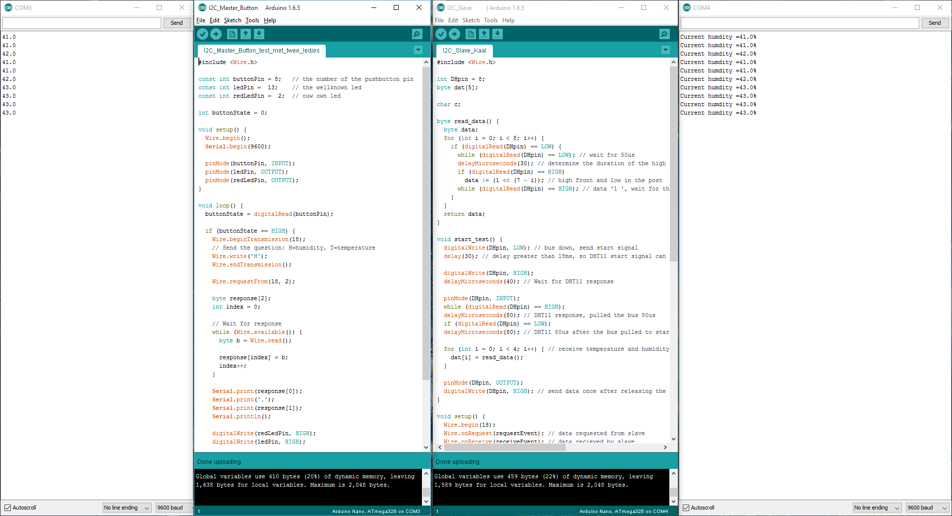
In my previous post I showed that it is possible to send a question (‘T’ for temperature and ‘H’ for humidity) to a certain Arduino (a slave address was provided) to receive the sensor data.

WP_20151028_13_56_23_Pro

This time I have taken the same slave but attached a Raspberry PI as master. There is one catch! I2C communicates at using the same voltage the master is using to function on. So watch out when attaching a 5 volt master to a 3.3 volt slave… In that case you need a I2C Logic Level Converter. But for now we are safe 🙂

public sealed partial class MainPage : Page
{
  public MainPage()
  {
    InitializeComponent();
  }

  private async void btnHumidity_Click(
      object sender,
      RoutedEventArgs e)
  {
    char request = 'H';

    var buffer = System.Text.Encoding.
                ASCII.GetBytes(new char[] { request });

    var response = await ReadI2CBus(18, buffer, 2);

    if (string.IsNullOrEmpty(response.State))
    {
      tbSent.Text = string.Format(
          "Humidity: {0}.{1}%",
          response.Response[0],
          response.Response[1]);
    }
    else
    {
      tbSent.Text = response.State;
    }
  }

  private async void btnTemperature_Click(
      object sender,
      RoutedEventArgs e)
  {
    char request = 'T';

    var buffer = System.Text.Encoding.
         ASCII.GetBytes(new char[] { request });

    var response = await ReadI2CBus(18, buffer, 2);

    if (string.IsNullOrEmpty(response.State))
    {
      tbSent.Text = string.Format(
            "Temperature: {0}.{1}°C",
            response.Response[0],
            response.Response[1]);
    }
    else
    {
      tbSent.Text = response.State;
    }
  }

  private async Task<I2CResponse> ReadI2CBus(
      int slaveAddress,
      byte[] buffer,
      int responseLength)
  {
    try
    {
      string aqs = I2cDevice.GetDeviceSelector("I2C1");

      var dis = await DeviceInformation.FindAllAsync(aqs);
      if (dis.Count == 0)
      {
        return new I2CResponse
        {
          State = "No I2C bus found"
        };
      }

      var settings =
            new I2cConnectionSettings(slaveAddress);

      using (var device = await
              I2cDevice.FromIdAsync(dis[0].Id, settings))
      {
         device.Write(buffer);

         var responseToFill = new byte[responseLength];

         device.Read(responseToFill);

         return new I2CResponse
         {
           Response = responseToFill
         };
      }
    }
    catch (Exception ex)
    {
      return new I2CResponse
      {
        State = ex.Message
      };
    }
  }

  private class I2CResponse
  {
    public byte[] Response { get; set; }

    public string State { get; set; }
  }
}

The I2C communication in written into a fairly simple method. This way it is very easy so send a message to a slave and receiving the response.

Using I2C to connect two Arduino Nano’s

This is part 1 of a series of blogs about device communication between Arduino, RaspberryPi etc:

  • Part 1: Using I2C to connect two Arduino Nano’s
  • Part 2: Using I2C between Rpi Master and Arduino Slave
  • Part 3: Use Bluetooth between Win 10 UWP and Arduino
  • Part 4: Add virtual Arduino ports to your UWP app
  • Part 5: Custom Firmata function called by Windows 10 IoT
  • Part 6: Better long running custom Firmata functions
  • Part 7: Custom servo usage in Firmata
  • Part 8: Using NRF24L01+ modules between Arduino’s
  • Part 9: Cheap Arduino mesh using RF24 radio modules

A few weeks ago I bought myself a collection of Arduino sensors, hoping I could use them directly on my Raspberry Pi. But I had forgotten that the Rpi does not have any analog ports so half of them were useless… for the Rpi.

For example, the Ky-015 Humidity and Temperature sensor for Arduino is a nice temperature and humidity sensor but it can not be used in conjunction with a Raspberry Pi.

Ky-015 Humidity and Temperature sensor for Arduino

But in my collection of IoT devices, next to the Raspberry PI 2B’s, I also have a couple of Chinese Arduino clones to play with.

So I was thinking, what if I use an Arduino to read the sensor information and then connect my Rpi to it to do some internet stuff with the information collected by the Arduino.

This is a very common scenario called a Gateway. The Rpi is slow but can communicate very easy with the internet (and it can hold an SSL key 🙂 ). And the Arduino is reading data near real-time but it has limited capacity for the program logic.

And the nice thing is that they both understand I2C, a protocol to communicate between devices. It works with master-slave relationships and the devices are connected by only two wires (and a third one but that’s just the ground wire). That’s easy!

I looked into this and this is my first experiment for communication between two Arduino Nano’s. It looks something like this:

I2C Nano Demo sketch_bb

The upper device is an I2C master has a button and a led. The lower is the I2C slave and holds the sensor. Master and slave are connected by the Black, White and Green wires.

Warning: Why is there no Rpi involved? First I wanted to be sure I understand I2C. Second, connection a Raspberry Pi and an Arduino is not without the danger of frying one or two devices (A Rpi is operating at 3.3 volts and an Arduino at 5 volts). I have seen documentation in which is stated that it can be done as long as the Rpi is the master.

The idea of this experiment is that when the master button is pushed, both the extra led and the internal led are lighted and a character (H for the humidity of T for the temperature) is sent to the slave. And the slave responds with the requested data. I use the serial port monitoring to check out the communication (part of the Arduino programming environment).

To make I2C communication extra easy, check the wire library. This makes I2C communication very accessible on the Arduino and the examples are good enough for the first experiments.

I want to warn here for false documentation due to wrong pinout description for Arduino Nano. Do not use the D4/D5 pinout! I wasted a lot of time using the wrong ports. The Arduino Nano uses GPIO A4 (SDA) and A5 (SCL) for I2C. Here is the right pinout for Arduino Nano:


Correct I2C pinout for Arduino Nano

Do you use another kind of Arduino, please check out your own pinout diagram!

So finally I came up with this code:

#include <Wire.h>

// I2C Master code for Arduino Nano 

const int buttonPin = 8;   // the number of the pushbutton pin
const int ledPin = 13;    // the wellknown led
const int redLedPin = 2;  // ouw own led
 
int buttonState = 0;
 
void setup() {
	Wire.begin();
	Serial.begin(9600);
 
	pinMode(buttonPin, INPUT);
	pinMode(ledPin, OUTPUT);
	pinMode(redLedPin, OUTPUT);
}
 
void loop() {
	buttonState = digitalRead(buttonPin);
 
	if (buttonState == HIGH) {
		Wire.beginTransmission(18);
		// Send the question: H=humidity, T=temperature
		Wire.write('H');
		Wire.endTransmission();
 
		Wire.requestFrom(18, 2);
 
		byte response[2];
		int index = 0;
 
		// Wait for response
		while (Wire.available()) {
			byte b = Wire.read();
 
			response[index] = b;
			index++;
		}
 
		Serial.print(response[0]);
		Serial.print('.');
		Serial.print(response[1]);
		Serial.println();
 
		digitalWrite(redLedPin, HIGH);
		digitalWrite(ledPin, HIGH);
 
		delay(1000);
	}
	else {
		digitalWrite(redLedPin, LOW);
		digitalWrite(ledPin, LOW);
	}
 
	delay(100);
}

I first send a character and then I wait for the response (two bytes). I communication with the slave at ‘channel’ 18. I2C makes it possible to communicate with multiple slaves, one at a time. So in theory, I could also check out another nano which is serving another sensor.

And next is the code of the slave. If you are not interested in the code of the sensor, just ignore ‘read_data’ and ‘start_test’:

#include <Wire.h>
 
// I2C Arduino Nano Slave
 
int DHpin = 8;
byte dat[5];
 
char c;
 
byte read_data() {
	byte data;
	for (int i = 0; i < 8; i++) {
		if (digitalRead(DHpin) == LOW) {
			while (digitalRead(DHpin) == LOW);
			delayMicroseconds(30);
			if (digitalRead(DHpin) == HIGH)
				data |= (1 << (7 - i));
			while (digitalRead(DHpin) == HIGH);
		}
	}
	return data;
}
 
void start_test() {
	digitalWrite(DHpin, LOW);
	delay(30);
 
	digitalWrite(DHpin, HIGH);
	delayMicroseconds(40);
 
	pinMode(DHpin, INPUT);
	while (digitalRead(DHpin) == HIGH);
	delayMicroseconds(80);
	if (digitalRead(DHpin) == LOW);
	delayMicroseconds(80);
 
	for (int i = 0; i < 4; i++) {
		dat[i] = read_data();
	}
 
	pinMode(DHpin, OUTPUT);
	digitalWrite(DHpin, HIGH);
}
 
void setup() {
	Wire.begin(18);
	Wire.onRequest(requestEvent); // data request to slave
	Wire.onReceive(receiveEvent); // data slave recieved 
	Serial.begin(9600);
	pinMode(DHpin, OUTPUT);
}
 
void loop() {
	start_test();
	delay(1000);
}
 
void receiveEvent(int howMany) {
	// remember the question: H=humidity, T=temperature
	while (0 < Wire.available()) {
		byte x = Wire.read();
		c = x;
	}
}
 
void requestEvent() {
	// respond to the question
	if (c == 'H') {
		byte response[] = { dat[0], dat[1] };
		Wire.write(response, 2);
 
		Serial.print("Current humdity =");
		Serial.print(dat[0], DEC);
		Serial.print('.');
		Serial.print(dat[1], DEC);
		Serial.println('%');
	}
	else {
		byte response[] = { dat[2], dat[3] };
		Wire.write(response, 2);
 
		Serial.print("Current temperature =");
		Serial.print(dat[2], DEC);
		Serial.print('.');
		Serial.print(dat[3], DEC);
		Serial.println('C');
	}
}

The slave is just checking the sensor, every second. Meanwhile, two callback functions can handle an I2C data received event and I2C data request event. First, we receive the character (H or T) which we store in a local variable ‘c’.

Next, we are asked for the answer so we check the local variable ‘c’ and answer with the right data.

Here is a screenshot on how it is working on my PC. On the left, the master is shown. To the right, the slave is shown:

I2C Nano Demo sketch_bb2

And as you can see, the data is exchanged as expected. This gives the confidence to start communication between my Rpi and an Arduino Nano.