A few days ago I bought this GPS receiver component from the internet It only costs less than 10 dollars, a fair price. Note: There are also components of five dollars or less. Check them out below.

The number on the module was xm37-1612 and it is a rather common GPS module, even used in drones.
This module needs 4 pins: ground, power (3.3V or 5V), TX and RX. So it communicates using a serial port.
So just solder the pins on the module. Keep the big ceramic antenna on top, and pins downs. I soldered the pins up too so it’s not possible to put in on a breadboard 😦
Then connect the module to the Arduino using power and ground and the RX-TX. For now use port 0 and 1 (on an Arduino Nano), RX on RX, TX on TX (which is strange, normally they have to be crossed… Maybe it’s just this type which is behaving strangely).
Now connect the Arduino to a laptop using the USB cable. It is really easy to test the module!
This is how… Just open up the Arduino Sketch IDE and select the right board (I use a Nano) and select the right Com-port for the USB (I use port 3). And the open up the serial (port) monitor. Select a communication speed of 9600 baud, the speed the module uses. If just needed to upload an empty project.
And there you have it, raw GPS information coming from your GPS module.

Note: this trick works for my Nano. My Leonardo is not showing anything… (Update: this is due to the differences in the design of the board. Pro tip: if you want to use other pins, check out Software serial. But also check out the board limitations, such as the Arduino design. I use port 8 and 9 for RX/TX on the Arduino)
As you can see, the messages are shown in plain text. And for the trained eye, it even makes sense 🙂 (Just like a scene from The Matrix).
The GPS gives a lot of information: your position, the position of the satellites in sight, your speed, your heading, your elevation (but pretty poor), UTC time and the quality of the measurement.
The quality is called DOP, dilution of precision and it is an indication of the accuracy of the fix. It ranged from 1 to 50 but a DOP less the 10 is considered poor.
Btw. A GPS also receives information from the satellites which is not passed to the user. I am talking about trajectory and frequency information. Most GPS satellites are not geostationary and once in a while their trajectory is changed to avoid collisions with other space debris (or the IIS or Martians). And every satellite communicates in a different way/frequency. This information is put into a table and has to be updated frequently so the GPS ‘knows when to listen and where’. Otherwise, it loses the ability to receive the right information.
High-level GPS devices (like a TomTom or Garmin) have the ability to upload the table from the internet (using some software tool provided by the company). But low-level modules have to receive it from the known satellites. This can take up to a couple of hours. So collect all your GPS devices you keep at home or in your car and let them run for a couple of hours.
So what do these lines of characters mean?
Each line is a certain sentence with specific information. Some sentences give the same information but overall they have their own usage.
For example, let’s look at:
| $GPGGA,123519,4807.038,N,01131.000,E,1,08,0.9,545.4,M,46.9,M,,*47 |
The $GPGGA means that this sentence contains the essential GPS information. The *47 is just a checksum of this line. If the checksum of the line does not match *47, just ignore this sentence. Serial communication is easily corrupted but you will get a new sentence in just a fraction of a second.
The information in the sentence is separated by commas and each value represents some vital information. Eg. 123519 is a Fix taken at 12:35:19 UTC (It is always today). 4807.038,N means Latitude 48 deg 07.038 seconds North and 01131.000,E means Longitude 11 deg 31.000 seconds East.
More detailed information is available at http://www.gpsinformation.org/dale/nmea.htm
Looking at this complex data, do you still want to know your position? 🙂 In 2005 I already parsed these sentences and it is very intensive. And that was written in C#, we are using an Arduino with another language now…
Do not worry, we do not have to parse the data on our own. Now TinyGps comes to the rescue. There are two version a default one and a newer TinyGPS++. Both are working for our module.
So download the software library and import it into the Arduino Sketch IDE. And let’s start using the test_with_gps_device example (or ‘fullexample’ if you use TinyGps++).
As you can see in the code of the example, you are able to adjust the baud rate in the code, the RX Port and the TX Port.
But because you are working using an actual device, please now attach RX to TX and visa-versa.
Now there is a catch! In my innocence, I adjusted the code so I used port 1 and port 0 (although the code was referring to port D4 and port D3). So it was not working… See how the checksum is failing…
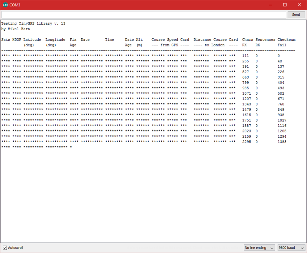
In other examples, I made the same mistake. It just gave a lot of corrupted characters. What was I doing wrong besides being stubborn?
Well as we have seen in the previous communication, the RX-TX line is used by the USB to fill the serial monitor. So the RX-TX is already in use! But officially this is the only possibility for serial communication.
Therefore, the example uses SoftwareSerial. This library simulates serial communication on other ports. So do not ignore port 4 and 3 🙂

If you experience lines full of stars but the checksum is zero, the communication could be ok… Please check RX is connected to TX etc.
So now you have some basic knowledge about both the working of GPS in general and specific knowledge about accessing your GPS module using TinyGps.
Update for Neo-6m-GPS module
Today I tested another GPS module, a Neo 6M module. It only costs $3.75, including shipping, so it was worth a trial.

The module at the top of this web page, pushes it’s NMEA messages over the RX/TX lines. So I just attach an Arduino Nano with an empty sketch and the raw GPS info appears in the debug window.
This Neo 6M module gave nothing…
untill, finally, I got the right information using the TinyGPS-13 library. Look in the Arduino IDE at the “simple GPS sketch”. Just connect:
- 5V to VCC and ground to GND.
- TX with port 4
- RX with port 3
Port PPS can be ignored (this is used for time/clock functionality).
And with that sketch, GPS info will arrive (in-house I connected to 7 satellites now). A led on the GPS module shows when data arrives at the module.
On the web page of the seller, a warning is given that the chip is old. But my GPS module gave good reception and accurate location. So, for less the four dollars I can recommend this GPS module. The module has a separate ceramic antenna (attached by a wire which contains some sticker (better leave it on, could be some interference filter)). This makes the module a bit fragile but also mode flexible to place in a casing.
Grove GPS Module
If you are not into GPIO but more into Grove base connectors, try out the Grove GPS Module. I have several sensors supporting the Grove connector and it is really simple to make a solution without any soldering. It’s ideal for setting up a quick test solution.
This GPS from Seeed Studio also has this serial interface for the NMEA protocol.
Sponsored message: Seeed Studio is the IoT hardware enabler providing services over 10 years that empower makers to realize their projects and products. Seeed offers a wide array of hardware platforms and sensor modules ready to be integrated with existing IoT platforms and one-stop PCB manufacturing and Prototype PCB Assembly. Seeed Studio provides a wide selection of electronic parts including Arduino, Raspberry Pi and many different development board platforms. Especially the Grove Sytsem help engineers and makers to avoid jumper wires problems. Seeed Studio has developed more than 280 Grove modules covering a wide range of applications that can fulfill a variety of needs.
